
Ever wondered how to safely wire a battery switch on your boat?
Proper installation is key to electrical safety and system reliability.
By the end of this guide, you’ll understand the essential steps to connect everything correctly and keep your boat’s electrical system running smoothly.
Keep reading for the full process.
Safety First: Disconnect Boat Battery Power Correctly
To disconnect a boat battery safely, you should always start by turning off all electrical systems, including lights, pumps, and electronics. Next, disconnect all shore power and charging sources to eliminate any current flow. This step is crucial to prevent electrical hazards. Treat every terminal as live, even when systems appear off, because residual voltage or damage can still pose a risk. If you need to charge your trolling motor battery while on the water, ensure you have the proper gear and follow smart charging tips to maintain safety. Work in a well-ventilated area to disperse any hydrogen gas produced during the process. Wear gloves and eye protection for added safety. Begin by disconnecting the negative terminal first; this minimizes the risk of short circuits if your tools contact any grounded metal. Secure the cable so it cannot swing back and touch the terminal again. Only after the negative terminal is secured should you proceed to disconnect the positive terminal. Use insulated tools to reduce sparking and avoid accidental contact with live parts. For long-lasting connections, consider brass or stainless steel terminals which offer superior corrosion resistance and current flow. A reliable battery maintainer can help extend the life of your marine batteries by preventing sulfation when the boat is not in use, making it the perfect match for programmers who dock their vessels for extended periods.
Keep cigarettes and flames far away from the battery to prevent ignition of hydrogen gas. Never lean over the battery while loosening cables, as dropping a metal tool can bridge terminals and cause sparks or explosions. If you plan to leave the battery disconnected for an extended period, fully remove both terminals to prevent parasitic drain. When reconnecting, connect the positive terminal first, then the negative, following the reverse process carefully to ensure safety.
Choose the Right Battery Switch: ON/OFF, 1/2/Both, or Selector
Choosing the right battery switch depends on your boat’s setup and electrical needs. An ON/OFF switch is ideal for single-battery systems or as a master disconnect to shut everything down quickly. For boats with two batteries, a 1/2/Both selector switch gives you flexible management: start or run on one battery, and reserve the other for emergencies by switching to “BOTH” only when needed. This setup allows you to prioritize maintenance or charge each bank separately. For a reliable setup, review comparisons of top battery switch options to ensure you select a model that matches your power demands. If you want automatic control over charging, consider a selective combiner switch, which manages battery connections without manual input. Always match the switch’s current rating to your engine’s starting power needs—models typically range from 175 amps to 300 amps. Never turn the switch to OFF while the engine is running; doing so can damage your alternator and electrical system. For lead acid batteries, using a solar charge controller ensures proper charging and prevents over-discharge. Additionally, sparking connections may indicate corrosion or loose terminals, which should be inspected and cleaned to prevent electrical faults.

Prevent Battery Drain: 12-48v battery switch is provide a convenient to disconnect the batteries from the electrical system, which refrains battery from draining during storage and isolate power in case of emergencies; Avert accidental discharge, electrical fires, helping you get the most out of your battery

Heavy Duty: ABS plastic housing, durable made for safety use, rear cover insulates terminals against any short of circuits. Design for 2 batteries vehicles, can switch battery 1 / battery 2 separately or both on and off.

Heavy Duty: ABS plastic Battery Disconnect Isolator Master Switch with 2 Removable Key Rust and corrosion resistant, Solid cooper nuts and brass washers.
Wire the Battery Switch Positive Cables Step by Step
Start by connecting the positive cables from each battery to the corresponding terminals on the switch. Use heavy-gauge red cable, ensuring the wire gauge matches your system’s total amp draw. Cut the cable to the appropriate length, strip the ends, and attach marine-grade ring lugs, crimping them securely. Connect Battery 1 to terminal “1” and Battery 2 to terminal “2,” verifying each connection matches your switch diagram. Always ensure the two batteries are of the same type to avoid system damage. For a trolling motor, the circuit breaker must be sized to handle the motor’s full load current without nuisance tripping, and you should choose a circuit breaker rated slightly above the motor’s amp draw. The overall longevity of these batteries depends on proper charging, usage cycles, and maintenance habits that directly affect their service life.
Next, run a common positive output cable from the switch’s output terminal to your boat’s main distribution point. Confirm the terminal labels before tightening the nuts and lock washers firmly. It’s crucial to install inline fuse protection near each battery to prevent overloads, and always use a marine fuse block to consolidate and protect all branch circuits. Route all cables so they are supported and protected from chafing, avoiding sharp bends or loose ties that could cause damage.
Finally, double-check every connection against your wiring diagram. Make sure all cables are correctly labeled, securely attached, and free of interference. Before restoring power, verify that inline fuses are in place and that no tools or loose parts remain in the engine compartment. Only turn on your system after confirming all connections are correct and secure for safe operation.

Permits selection between batteries for starting, charging or operation in parallel

5 Pin Rocker Switch: Nilight 5 pin on-off rocker switch with SPST design (single pole single Throw), simple installation, freely turn on or off the light. Built-in two premium LEDs Emits soft light to illuminate the patterns, easy for you to find the switch in the dark.

Function: The Voltage Sensitive Relay (VSR) ensures that the primary battery is always charged and ready to start the vehicle by cutting in at 13.3 volts and cutting out at 12.8 volts. When your engine is turned on and the starting battery is fully charged, the isolation will start charging the second (auxiliary) battery at the same time. Enables you to charge two batteries from one alternator at the same time.
Route Negative Cables to the Bus, Not Through the Switch
All negative cables should be connected directly to a common negative bus or the battery negative terminal. This includes engine negative, panel negative, and accessory negatives. Routing negatives this way improves wiring organization and maintains a continuous DC negative side, which compliance standards require. Never route negative conductors through the switch, as doing so can interrupt the return path and cause loss of ground reference for your loads and charging equipment. The switch is intended solely for positive isolation. A dedicated negative bus consolidates all return paths into a single, accessible point, reducing wiring complexity and ensuring a stable ground. For boat owners, inverter run time is directly affected by how cleanly the DC negative path is maintained, since a poor ground increases resistance and wastes energy. This is particularly important when charging, as a poor return path can prevent deep cycle battery from reaching full capacity. Size the bus to match your feeder ampacity and place it close to your distribution area for shorter cable runs, as cable length is a critical factor in voltage drop and system performance. Every termination should be securely fastened to minimize resistance and maintain a reliable connection.
Mount the Switch and Torque Terminals to 13.5 N·m
Mount the switch close to the batteries on a flat, accessible surface to keep high-current cable runs short and reduce stress on the housing. Follow the manufacturer’s mounting pattern, typically using #10 screws, but avoid over-tightening to prevent deforming the switch body. If mounting on a rear panel, remove only the necessary access plate and ensure the upward-facing side remains sealed against water. When connecting cables, apply dielectric grease to the terminals to prevent corrosion and ensure a secure, low-resistance connection. An AGM deep cycle battery is often recommended for boats because it provides reliable power without outgassing, making it safer for enclosed compartments. Using a battery charger with maintainer can further extend the life of your AGM batteries by keeping them at optimal charge when the boat is not in use.
Set your torque wrench to 13.5 N·m (120 in-lb) before mounting the terminals. Apply this torque to each terminal stud carefully—do not guess by feel. Using a calibrated tool helps prevent under-tightening, which could loosen lugs, and over-tightening that might strip the studs. Make sure lock washers and nuts are stacked correctly and that lugs are aligned so tightening does not twist the assembly. After the switch is seated properly on its mounting surface, recheck the torque on all terminals to confirm they are secured to the proper specification.

【Precise Torque Control|±3% High Accuracy】 HERONIX 3/8 torque wrench provides a working torque range of 5–50 Ft-Lb (6.8–67.8 Nm), ideal for precise mechanical adjustments. Each torque wrench 3/8 drive is factory-calibrated to ±3% accuracy and verified through extensive testing to ensure consistent performance. Perfect for spark plugs, bike components, and automotive repair.

PRECISION & RELIABILITY - Manufactured in Taiwan and pre-calibrated to an accuracy of +/- 4%, ensuring dependable results. Includes a calibration certificate with a traceable serial number, so you can trust in the precision of every use.

Test Voltage, Continuity, and Start From Each Bank
Ensure there is no continuity between the battery input and load output when the switch is OFF. With the switch in position 1, only Battery 1 should connect; in position 2, only Battery 2 should connect. When set to BOTH, both battery inputs should connect to the common terminal. Use a continuity tester or multimeter set to measure resistance. If continuity is detected in any position where it shouldn’t be, it indicates a defective switch or a wiring error in the terminal connections. Proper testing confirms the switch functions correctly and the wiring is correctly established. For comparison, when selecting shore power inlets, stainless and plastic options present trade-offs in performance, cost, and lifespan that may guide similar wiring decisions. Similar to selecting a reliable shore power system, a SmartPlug connection offers enhanced safety and a lower risk of arcing compared to traditional inlets. To verify the switch’s isolation, you should also measure voltage drop across the terminals while under a small load to confirm there is no unintended leakage.
Avoid These Common Battery Switch Wiring Mistakes
When wiring your battery switch, don’t assume terminal functions—always follow the manufacturer’s diagram to ensure proper connections. Incorrect selector-terminal mapping can cause confusing behavior, and reversing leads may result in unexpected dead starts. Keep DC negative connections separate from the switch; routing the negative through the switch increases short-circuit risks. Never use BOTH as a normal operating position because it’s meant exclusively for emergency starts. Avoid switching through OFF while the engine is running, as this can damage your alternator. To prevent corrosion and ensure reliable connections, keep terminals clean, tight, and properly terminated. Loose or corroded terminals cause voltage drops and overheating, so always torque studs correctly and shield them from moisture. Before starting, verify that the common post connects solely to engine and house loads, while each battery post links only to its intended battery source. For a safer installation, confirm that all cable routing avoids sharp edges and uses proper strain relief to prevent chafing and vibration damage. Additionally, always use marine-grade tinned wire to resist corrosion and ensure long-lasting conductivity in the damp environment.

Advanced Dual Battery Isolator 12V Kit – Designed for superior performance, this dual battery kit ensures efficient power distribution between two batteries without voltage drops. Unlike traditional battery isolator diodes, this automatic disconnect switch eliminates power loss while maintaining a seamless connection between your primary and auxiliary power sources. Compact at 2.6” x 2.6” x 2”, it’s perfect for under-hood installations or as part of a battery relocation kit.

High Current Battery Switch: With a rated current of 200 Amp Continuous, and 1000A Intermittent, Spurtar battery disconnect switch safely isolate and secures 12-48V DC electrical system connections
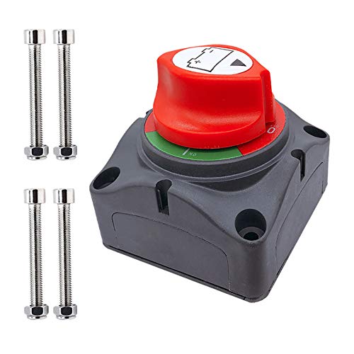
Heavy Duty: ABS plastic housing, durable made for safety use, rear cover insulates terminals against any short of circuits, equiped with 4 sets of bolts.