
Ever wondered how to properly test a marine circuit breaker? It’s a key step in ensuring your boat’s electrical system stays safe and reliable.
By checking the breaker’s condition and functionality, you can catch issues early before they cause bigger problems. Follow these straightforward steps to make sure your breaker is working correctly and ready to protect your system.
Why Marine Breaker Testing Requires Extra Precautions
Marine breaker testing requires extra precautions due to the unique hazards present in a saltwater environment. Salt mist accelerates insulation degradation, so you must inspect every connector for corrosion before testing. Frequent engine vibration can loosen terminals, leading to false readings—check and tighten these connections regularly. The risk of ignition is heightened around marine fuel vapors, so always treat breakers as potentially dangerous. Arc-flash energies near marine environments can exceed 40 cal/cm², making protective gear essential. Confirm that your testing equipment conforms to specific marine electrical certification standards. Insulated mats and tools are not optional; they provide critical protection in wet and conductive conditions. Grounding integrity is vital—poor bonding can distort fault behavior and safety measures. Always perform insulation resistance tests before engaging any active testing to ensure equipment health. Remember, degraded gear stores energy that can cause unexpected shocks or arcs. Due to these heightened risks, every step must be undertaken with careful discipline to ensure your safety. Spark-causing corrosion on shore power connectors is a common root cause of arcing that must be inspected before testing. Choosing high-quality terminals with corrosion-resistant materials can reduce failure points in the circuit path.
Step 1: Kill the Power and Confirm It’s Off
Before you begin working on a circuit, you must ensure it is fully de-energized. Identify every power source feeding that circuit—batteries, inverters, generators, shore-power connections, and any upstream disconnects. Remember, hidden backfeed paths through marine wiring or breaker accessories can still energize the circuit. Shut down equipment using its normal controls first, then open the breaker. Physically isolate the circuit by applying lockout/tagout devices if required for your vessel. Confirm the breaker remains fully open before proceeding. For a portable power source during this initial shutdown, consider a portable solar panel that includes plug sockets to maintain a safe, independent testing area. When selecting replacement components for your vessel, review a fuse block for LS swap to ensure your setup handles the necessary amperage.
Next, acquire a properly rated voltage tester suitable for the circuit’s voltage range. Test the tester on a known live source to verify it is functioning correctly. Then, check for zero voltage at the work point by measuring phase-to-ground and phase-to-phase. Never rely solely on a non-contact detector; always verify with a contact tester. After confirming the circuit is dead, recheck the tester on a live source to ensure it’s working properly. If you detect any voltage, stop immediately, re-examine for possible backfeed or stored energy, and treat the circuit as live until you are completely confident it is de-energized. For a reliable initial check on the breaker itself, consider using quality wire strippers with built-in voltage sensing to confirm live status before testing downstream.
Step 2: What to Look For in a Bad Marine Breaker (Visual Signs)
Once the power is confirmed off, inspecting your marine breaker for visible issues is essential. Focus on three key signs: overheating, corrosion, and physical damage. Look for brown or scorched discoloration on the breaker body, which indicates excess heat that could signal internal faults or overloads. Melted plastic or soot around the unit also point to failure and should never be ignored.
In salty marine environments, greenish oxidation on terminals and white crystalline salt deposits are common but serious signs of active corrosion. These weaken contact points, increasing the risk of failure. For emergency isolation, consider a system using a kill switch with lanyard as an additional safety layer. Additionally, check for cracks, fractures, or a loose handle—any physical damage compromises the breaker’s structural integrity and functionality. Heat discoloration on adjacent panel parts suggests overload stress and potential damage expansion.
If you notice any combination of these visual cues, do not attempt repairs. Instead, replace the breaker immediately to ensure safety and reliable operation. Treat these signs as critical red flags, not superficial issues to be brushed aside during routine cleaning.

Protect your system: using as circuit breaker and battery Disconnect, allows to charge or maintain the battery without having to disconnect all the wires; Protect excessive current between battery or electrical from damage

Manual reset: Visible reset lever shows open condition, unique push button reset Can also be used as a kill switch; Button on circuit breaker can act as a master disconnect for circuits

Product Name: Compact, Single Pole, Push-to-Reset Thermal Circuit Breakers
Step 3: How to Manually Reset and Test the Marine Breaker
To manually reset and test the marine breaker, first ensure circuit safety by shutting off both shore power and main battery switches. Then turn off the load connected to the breaker, and verify the area is dry to prevent electrical hazards. Locate the breaker, which will be in the off position or have a popped-out button indicating a trip.
Match the breaker style. For push-to-reset types, press the button firmly until it clicks into place. For toggle-style breakers, move the handle fully to off, then carefully back to on. Reset slowly and with steady pressure to ensure proper latching. A successful reset will usually produce a click or cause the lever to latch back into the on position. This action restores electrical flow to the circuit, but only after addressing the cause of the overcurrent is crucial to prevent recurrent tripping. Using a heat gun on nearby wires can help dry moisture that may contribute to the fault. For systems with multiple batteries, using a trickle charger can help maintain consistent charge levels and prevent false breaker trips. You should also check for any visible corrosion on the breaker terminals before restoring power.
Restore power and turn on the connected device. If the breaker remains steady, it has successfully reset and is functioning properly. If it trips immediately after restoring power, there is likely an unresolved fault in the circuit. In that case, do not attempt to force the reset again. Remember, proper breaker maintenance involves knowing when to stop and when further troubleshooting or replacement is necessary.

Branch circuit breakers (can also be used for 24-hour circuit protection)

Pack of 2, white CLB circuit breaker waterproof boots, thread material: nickel-plated brass, thread: 3/8”-27
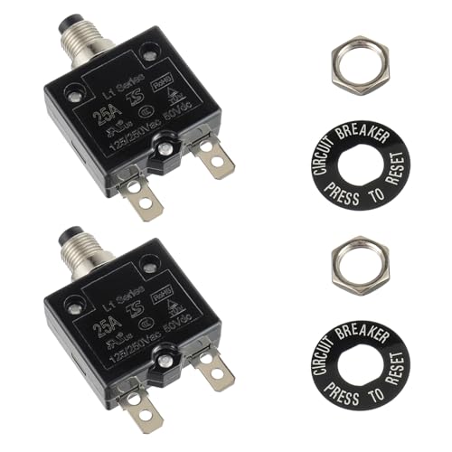
Product: Compact, single pole, push-to-reset thermal circuit breakers, Thermal Overload Protector L1 Series.
Step 4: Use a Multimeter for a Continuity Check on the Breaker
Using a multimeter for a continuity check on the breaker verifies if the internal contacts are closing properly when the breaker is in the ON position. First, set your multimeter to continuity mode (look for the sound-wave icon) or to measure resistance in ohms (Ω). Confirm the meter works by touching the probes together—you should hear a beep or see a near-zero ohm reading. Next, disconnect the load wire from the breaker, turn off all power sources including shore power and battery feeds, and ensure the breaker is isolated. Place one probe on the input terminal and the other on the output terminal, keeping firm contact. A beep or an ohm reading close to zero indicates the breaker’s contacts are closing properly and the breaker is likely good. No beep or an open circuit reading suggests the breaker may be broken or has an open internal path. Remember, when the breaker is OFF, it’s normal to see no continuity. If your readings fluctuate or seem inconsistent, double-check the isolation before considering replacement. For terminal connections, use a crimping tool with cutter to ensure secure, reliable wire attachments. For powering the testing process, a solar charger for lithium batteries can maintain a consistent voltage supply for your multimeter. Boaters should also verify that their AGM battery is properly protected by the breaker to avoid performance issues during operation.

ACCURATE CIRCUIT BREAKER IDENTIFICATION: Quickly locate the correct breaker with precision using the transmitter and receiver of the circuit breaker finder, ensuring efficient electrical troubleshooting

All-in-One Circuit Diagnosis: KT301P circuit breaker finder Easily locate breakers, check outlet wiring, and test GFCI protection—all with one compact tool. Combines a Circuit Breaker Finder, Outlet Tester, and GFCI Tester for fast, reliable troubleshooting on North American 120V AC circuits in residential or commercial settings
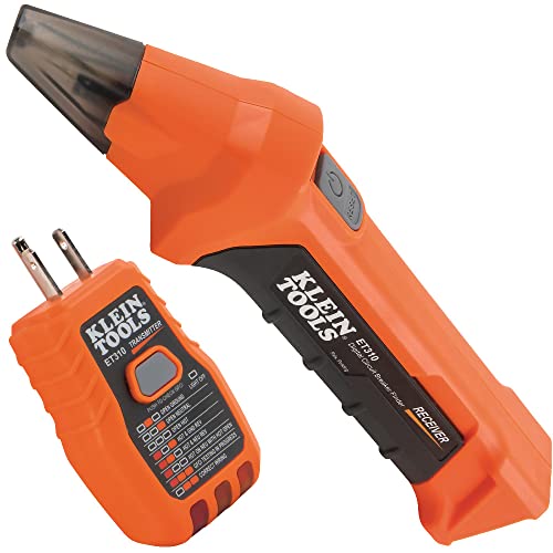
ACCURATE CIRCUIT BREAKER IDENTIFICATION: Quickly locate the correct breaker with precision using our circuit breaker finder, ensuring efficient electrical troubleshooting
Step 5: Live Voltage Test-What the Numbers Tell You
If you see a significantly lower output during a live voltage test, it indicates a resistance measurement problem. A voltage drop over 0.2 volts points to poor connections, corrosion, or partial internal failure. When the voltage drop exceeds 0.5 volts, it signals a serious overheating risk that could lead to damage or failure. Zero output, despite voltage being present at the input, means there is an open breaker or a broken circuit. For boat owners, charging on water demands extra attention to these voltage readings to prevent battery system failures. A marine battery’s charging time can vary dramatically based on battery type and charger output, so monitoring live voltage is essential for catching issues that might otherwise go unnoticed. Knowing whether you prefer circuit breakers or fuses can also help you decide if a failing breaker should be replaced with a more durable solution.
These live readings are crucial because a breaker might appear to pass a no-load test but can still fail under actual current. Monitoring the voltage and noting the voltage drops helps you catch hidden issues that aren’t evident through static inspection. Always measure across connections and components while the circuit is live to ensure safe and accurate diagnosis of your marine electrical system.
Step 6: When a Pro Should Perform Load Testing on Your Breaker
You should call in a professional to perform load testing on your breaker when its behavior deviates from expected protection. This includes instances such as tripping immediately after reset with a cleared load path or when branch circuits fail one after another, indicating a deeper fault that repeated resets cannot fix. Professionals use high-current test sets, sometimes reaching up to 8,000 amps, to verify that the breaker’s calibration aligns with manufacturer specifications—something you cannot do on your own. They also conduct comprehensive load spectrum tests, covering everything from low loads to fault conditions, to ensure the breaker is functioning correctly under all scenarios. Professionals often recommend pairing a tested breaker with a reliable master switch to manage overall system safety. This process guarantees safety, regulatory compliance, and provides traceable documentation for insurance purposes. Since load testing requires specialized equipment and controlled conditions, it’s safest to have a marine electrician handle the job rather than attempt it yourself. For similar reasons, a battery switch is often recommended by experienced boaters to isolate power and prevent electrical fires.

All-in-One Circuit Diagnosis: The KT302P Circuit Breaker Finder is designed for fast, intuitive troubleshooting. It easily locates breakers, checks outlet wiring, and tests GFCI protection—all in one compact tool. Combines a Circuit Breaker Finder, Outlet Tester, and GFCI Tester for fast, reliable troubleshooting in residential or commercial settings

All-in-One Electrical Diagnosis: The KT303P Circuit Breaker Finder Tools quickly locate breakers, check outlet wiring, test GFCI protection, and non-contact voltage testing in one compact tool. The innovative nesting design allows the transmitter and receiver to store together securely, reducing the risk of misplaced components while improving portability for residential and commercial electrical troubleshooting

All-in-One Circuit Diagnosis: Combines Circuit Breaker Finder, Outlet Tester & GFCI Tester – Quickly locate breakers, test outlets (open ground/reverse polarity), and verify GFCI protection in one compact tool. Includes essential accessories: light socket adapter (for lamp circuit testing),3-prong to 2-prong grounding adapter and alligator clip adapter (can be used for bare wire). Perfect for troubleshooting home wiring or commercial systems
Step 7: Why Your Marine Breaker Trips Immediately After Reset
If your marine breaker trips immediately after you reset it, there is likely an active fault present on that circuit, not just a random nuisance. This situation indicates a short circuit or a hard ground fault. The breaker’s magnetic trip function responds to dangerously high fault currents, so repeatedly resetting it won’t resolve the problem. Instead, it can cause further damage or create a safety risk. Unlike a standard household breaker, a thermal circuit breaker is designed primarily for overloads rather than instant high-current faults, but the magnetic component in marine models handles these dangerous spikes.
To diagnose the issue, start by unplugging all connected loads. Damaged appliances or wiring—such as pinched, cut, or melted conductors—often create a permanent fault path that triggers the breaker instantly. Moisture intrusion, common on boats, can also cause ground faults through corroded insulation or water-damaged outlets. If the breaker continues to trip immediately after all loads are disconnected, suspect the breaker itself, though this is less common. Always eliminate external faults first before considering replacing the breaker.
Step 8: Check Terminals for Corrosion and Loose Connections
Check terminals for corrosion and loose connections by inspecting copper terminals for green or white buildup, which indicates oxidation and salt exposure. Look for rust, burn marks, or melted insulation that signal poor contact or overheating. Perform a tug test on all connectors; if a Marine connector shifts, tighten it securely to prevent resistance and heat buildup. Clean light corrosion with electrical cleaner and a wire brush, then dry thoroughly. Applying dielectric grease helps prevent future corrosion. Focus on high-current joints like bus bars and breaker terminals, and always check for water intrusion, as moisture accelerates decay. A clean, tight terminal restores efficiency and prevents voltage drops. If the connection remains firm after cleaning, this indicates the terminal is properly secured and not the source of any faults. For boats using shore power, managing power with a battery disconnect switch ensures these terminals remain isolated when not in use. Choosing the correct battery group size like 24 or 27 ensures the terminals match the amperage demands without overloading the circuit.


【CLEAN & PROTECT KIT】Includes 2 battery terminal cleaners and 12 anti-corrosion fiber washers (6 red, 6 green) for a complete battery terminal care set. Clean corroded connections, then add washer protection to help reduce future buildup

Specially designed to protect battery terminals from corrosion, a leading cause of hard starting and battery failure.
Step 9: Replace the Breaker If It Fails Any of These Tests
If a breaker fails to reset after clearing the load or won’t trip during testing, it must be replaced immediately. A non-trip-breaking device offers no protection, increasing the risk of electrical faults or damage. Visible signs of damage such as heat discoloration, cracked housings, or corrosion from salt spray also indicate the breaker is compromised and needs replacement. Ensure your new breaker matches the circuit’s voltage, amperage, and adheres to ABYC standards. This model is a 40A 32V panel mount marine circuit breaker from Mechanical Products MP, compatible with Mercruiser, Indmar, and Volvo. Always use marine-rated components because non-marine breakers cannot withstand the vessel’s harsh environment. Secure all wiring connections, particularly at the marine connector, to prevent future faults. After installing the new breaker, test it thoroughly before restoring power. Regular battery maintenance should include verifying the breaker’s proper function—it’s a simple step to ensure your electrical system’s safety and reliability. Replace faulty breakers promptly and follow your boat’s specifications for a safe, dependable electrical setup.