
Wondering how to check if your battery isolator is working properly? A simple multimeter test can help you identify issues like blown diodes or faulty wiring without much hassle.
By measuring voltage at different points, you’ll quickly see if the isolator is allowing current flow as it should.
Keep reading for step-by-step instructions to make testing straightforward.
Prep Your Multimeter and Ground for Isolator Tests
To ensure accurate isolator tests, you need to properly prepare your multimeter and establish a solid ground connection. Start by verifying that your test leads are undamaged, clean, and firmly inserted into the voltage jacks. Check your multimeter’s battery voltage against a known baseline to confirm it is functioning correctly, as this is vital for reliable readings. For grounding, prefer connecting the black lead to the negative battery post rather than the cable end, as the post provides a more consistent reference point. Knowing your Group 24 battery weight helps you plan the battery’s physical placement and connection to the isolator. A top battery disconnect switch can also serve as a reliable cutoff point for isolating circuits during testing. For quality and performance, best battery terminals ensure a secure connection that minimizes resistance in the isolator circuit.
Touch the black lead to the verified ground point and the red lead to the isolator terminal you want to test. Maintain steady contact pressure to prevent fluctuations in the reading. It is important to monitor the reading closely; if it varies significantly, recheck the ground connection to rule out a poor reference. Avoid metal surfaces that are painted or corroded, as these can distort your measurements. Holding the black lead steady on a confirmed ground ensures that any voltage readings you’re seeing are accurate reflections of the isolator’s condition, not errors introduced by a faulty reference point.

[Great value, full set] our test lead set comes with two additional professional alligator clips (Alligator Clips). This means you can achieve "hands-free" convenient operation without paying extra. It is very suitable for long-term voltage monitoring or connecting hard-to-reach test points. The cost-effectiveness is obvious at a glance.

【Upgraded Full Accessories】This 92PC automotive test leads boasts more abundant terminals and accessories than the 68PCS basic multimeter leads kit. It contains 72 multi-size round and flat terminal adapters covering multiple specifications, plus 5KΩpotentiometers, LED stroboscopes, insulated alligator clips, piercing probes, 1 to 2 connectors and dedicated SRS connectors. Our terminal test kit fit most European, American and Asian vehicle wiring plugs, meeting complex testing demands of ECU, sensors and solenoid valves without extra adapters.

Soft, Safe and Excellent Quality: The upgraded version of the product, the leads are made of high quality silicone, cold and high temperature resistant, very soft, more flexible use. A double insulated lead with 100 high-purity copper wire ensures safety, low resistance and no signal loss. The products are well designed and made.
Set Your Multimeter Correctly for Diode Isolator Testing
Test the diode only on a de-energized circuit after discharging any capacitors to avoid false readings. A healthy silicon diode will show a forward bias voltage between about 0.5 V and 0.8 V. In reverse bias, it should display OL (over limit or no reading). If both directions show a reading, the diode is shorted; if neither shows a reading, it is open. Compare the forward and reverse measurements directly, as differences indicate potential diode degradation or current leakage. To ensure accuracy, keep the test leads stable and maintain firm contact with the diode terminals to prevent false readings. For a reliable battery system, always pair a properly tested isolator with a high-quality master switch, and understand how that switch interacts with shore power connections to avoid unexpected drain.

【High Safety Performance】 - The test leads can be safely used for CAT III 1000V and CAT IV 600V rated current test of 20A, suitable for professional electrical testing. Universal 4mm banana plug, compatible with digital multimeters, clamp meters, and desktop multimeters, adapting to different working environments.
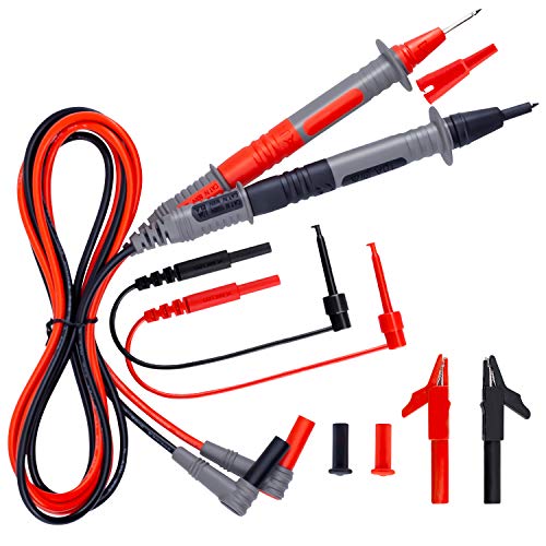
SECURITY LEVEL AND HEAVY DUTY - It is safe to test CAT III 1000V &CAT IV 600V rated current 10A current, perfectly fits all kinds of multimeters like clamp meters, digital multimeters, table meters

Accurately Test Full Features: Accurately measures AC/DC voltage, DC current, resistance, continuity test, diode and batteries.
Engine-Off Voltage Test on Each Isolator Terminal
To perform an engine-off voltage test on each isolator terminal, start with the diode check completed and your multimeter set to DC volts. Probe each outside terminal against a known good ground. For a healthy, fully charged battery, you should see a voltage reading between 12.4V and 12.8V on each outside terminal. A dual battery switch can simplify isolating these circuits manually, but this test verifies the isolator itself. Any variation between the two outside terminals is normal and reflects the battery’s capacity, not isolator loss. This baseline helps evaluate alternator efficiency later. A low reading on one terminal might indicate a faulty battery isolator or a related battery problem. Next, check the center terminal. It should typically read 0 volts when the engine is off. A voltage reading here indicates a failed diode that breaks isolation. Confirm proper engine-off isolation if both outside terminals show similar voltage and the center reads zero. If one outside terminal reads low, it usually points to a battery issue rather than an isolator failure. This quick test ensures there are no unintended current paths between your batteries. For example, if the low terminal corresponds to a Group 24 battery, its lower capacity compared to a Group 31 may explain the voltage difference.

【Reliable Car Battery Tester】: The alternator tester can accurately determine whether the car battery needs to be replaced or if there is a power outage, and at the same time evaluate the output status of the alternator, clearly presents real-time voltage data, battery health and charging status. It can effectively prevent the battery from being damaged due to overcharging or undercharging, and extend the battery's service life.

Effortless Operation - Boasting a “plug-and-test” design, there's no need for complex set-up procedures. Just connect it to the battery following simple steps. Without starting the vehicle, you can read the battery status, and after starting, quickly obtain the alternator status. Whether you're a professional mechanic or an ordinary car owner, you can easily use it to quickly determine if the battery needs jump - starting, replacement, or if the alternator output is normal.

Catch Battery Problems Early: Featured in two videos by Project Farm, a popular YouTube channel with millions of subscribers, the ANCEL BA101 helps you quickly spot battery issues before they leave you stranded. It provides easy-to-understand readings for State of Health (SOH), State of Charge (SOC), voltage, current, CCA, plus cranking and charging system tests, so you can better understand your battery and help avoid unexpected breakdowns
Interpret Zero Volts on the Center Terminal Correctly
Seeing zero volts on the center terminal with the engine off is normal because the alternator isn’t generating power. However, this reading alone does not confirm that the isolator is functioning properly. Zero volts can also indicate an open circuit, a blown fuse, or a disconnected alternator feed. You still need to verify the isolator’s integrity by checking the outside posts for battery voltage. Later, when the engine runs, confirm that charging voltage arrives at the center terminal. This step is essential to rule out wiring faults or a failed isolator diode, as zero volts does not guarantee overall system health. Understanding the deep cycle battery lifespan helps you recognize when voltage drops may indicate worn batteries rather than isolator issues. Consider this reading as a baseline—do not interpret it as a pass or fail. Always supplement your test with a check of the kill switch lanyard circuit to ensure emergency shutdown components are not inadvertently affecting the isolator readings. A shorted shore power cord can also introduce stray voltage that interferes with your isolator readings and battery charging system.
Start the Engine and Check Charging Voltage at Each Post
Start the engine and set your multimeter to DC volts, typically the 20 V range for a 12 V system. Place the black probe on a clean ground, such as the engine block or battery negative terminal, then touch the red probe to the center post, which connects to the alternator. A proper reading should be between 13.8 and 14.5 volts, indicating the alternator is charging the system. If the voltage remains near the static battery voltage, usually around 12.6 volts or lower, the alternator isn’t providing charge. A similar voltage check is performed when resetting marine circuit breakers after a fault. Next, move the red probe to the engine battery post. It should read close to the center post voltage. A small difference — up to about 0.2 volts — is normal due to isolator or wiring variations. However, a large voltage drop suggests excessive resistance in the wiring or connections, which can impede charging. The chemistry and maintenance schedule of your battery influence overall health, but don’t directly affect this voltage test. For long-term reliability, pairing your system with a top solar battery maintainer can help keep batteries fully charged when the engine is off. Even without a traditional alternator, a portable solar panel can supply equivalent charging voltage when connected to the battery terminals. Finally, check the house battery post by placing the red probe there. It should also show a voltage within the same range, typically 13.8 to 14.5 volts, when the engine is running. If the house battery voltage remains at rest level while the engine post voltage rises, it indicates the isolator isn’t passing charge properly. Equal or similar voltages across all posts confirm that the isolator is functioning and charging is evenly distributed.

【PRECISE READOUTS & CLEAR DIGITAL DISPLAY】Bright LED display shows highly clear readings in any lighting condition, 0.1V resolution gives you reliable indication and shows you the voltage number easily & quickly. Bidirectional light emitting diode on the circuit board for easy battery load testing, red light indicates positive polarity, green light indicates negative polarity.

Versatile Digital Multimeter - Accurately measures AC/DC Current, AC/DC Voltage, Capacitance, Frequency, Duty Cycle, Resistance, Diode, Continuity and Temperature.

Customer Service: KAIWEETS provides a lifetime after sale service and technical support. This digital multimeter is included with 2 AAA batteries (pre-installed), comes with a carrying case and 2 decent cable leads.
Voltage Drop Test: Spot a Failing Diode Leg
To identify a failing diode leg, perform a voltage drop test with the engine running. Set your multimeter to DC volts. Measure from the center alternator terminal to each output leg of the isolator. A healthy diode shows a small forward voltage drop, typically between 0.3 V and 0.45 V. If one leg exhibits a much higher drop, it indicates excess resistance or a failing diode. When one output leg consistently reads lower than the other, that leg’s diode is likely problematic. For designs with near-zero voltage drops, check the isolator specifications; any measurable voltage loss suggests an issue. Remember, wiring faults usually cause different problems. First, test the isolator output voltage, then verify the wiring from the isolator to the battery. Low voltage at the isolator output points toward a faulty diode leg rather than downstream wiring. Unequal voltages during charging are the clearest signs of a failing diode.

HIGH COMPATIBILITY: It is not only suitable for AA, AAA, C, CR123A, D, 9V, N, CR2, CRV3, 2CR5, CR-P2 cylindrical battery testing, but also good for checking a wide variety of button cell batteries

【Package Content】 - 2 Pack battery tester, Opp bag. Weight light and easy to carry.

MULTI PURPOSE USE- can be used to test different type of household batteries like AA, AAA, C, D, 1.5V,9V and 1.5V button type
Diode-Direction Test: Forward and Reverse
To test if the isolator’s diodes function as one-way valves, use your multimeter’s diode test mode to check them in both forward and reverse bias. Begin by connecting the red probe to the diode’s anode and the black probe to the cathode. A healthy silicon diode should show a stable voltage reading between 0.5 and 0.8 volts, indicating conduction in the correct direction. For lead acid batteries, selecting a charge controller with a proper regulation algorithm ensures optimal charging and prevents overvoltage damage.
Next, switch the probes: connect the red to the cathode and the black to the anode. A properly functioning diode should block current, resulting in a reading of OL or infinite resistance. If you see a measurable voltage or a low reading during this reverse test, it indicates leakage or a short circuit. If the diode shows a forward voltage in both directions, it has failed. An OL reading in both directions suggests the diode is open. If the reading is similar regardless of polarity, the diode isn’t functioning as a one-way valve, and the isolator should be considered faulty. For reliable power safety, consider reviewing top battery disconnect switches after confirming isolator health.
Use Continuity Mode to Confirm One-Way Current Flow
Use continuity mode to confirm one-way current flow. Start by powering off the circuit and setting your multimeter to continuity mode, indicated by a symbol resembling a sound wave or diode. Insert the black lead into the common (COM) port and the red lead into the V/Ω port. Touch the probe tips together to verify the meter beeps, confirming the setup is correct.
Next, place the probes across the isolator’s forward path. You are checking for one-way current flow; a beep in the forward direction confirms continuity. Conversely, no tone in the reverse direction proves proper isolation. This directional behavior functions like a one-way valve, preventing reverse current that could harm battery performance. If you hear isolator noise only in one direction, it indicates the device is working correctly. No beep in either direction signals an open path, while beeps in both directions suggest a shorted diode. To ensure accurate results, keep probe contacts clean and test on a dry, de-energized circuit, and always verify that your wiring and connections match marine safety standards to prevent corrosion or faults. Matching your charger’s output amperage to the isolator’s rated capacity prevents overloading the diode and ensures safe charging for your house and starter banks. For optimal charging, pair your system with a top-rated lithium charger that maintains stable voltage without overcharging the bank.
How to Interpret Voltage Drops and Continuity Readings
Voltage drops above 0.50 volts on the power side indicate excessive circuit resistance. To accurately diagnose, you must perform voltage drop testing with the circuit on and loaded, simulating real-world conditions. Each connection point should register under 0.20 volts; higher readings suggest issues like corrosion or poor crimping. If you notice voltage fluctuation under load, it points to intermittent internal resistance in the isolator. For example, if the battery terminal reads below 13.6 volts while the alternator side is higher, this signifies a significant voltage drop needing correction. For high-current marine systems, selecting the correct battery cable gauge ensures minimal resistance and prevents excessive voltage drops.
Continuity testing is simpler: when you hear a beep, the circuit has a low-resistance path. However, a good continuity reading alone doesn’t guarantee proper circuit performance under load. It confirms only that a connection exists, not that it can handle real-world electrical demands. Therefore, rely more on voltage drop measurements for diagnosing charging faults since they better reflect actual circuit conditions.
Wiring Issues That Mimic a Bad Isolator
Wiring issues that mimic a bad isolator are among the most common culprits behind a seemingly dead battery isolator, even when it’s actually functioning properly. One primary problem is battery corrosion on terminals or lugs, which disrupts the charging flow and gives the illusion of a faulty device. Loose connections can cause intermittent power delivery, making the isolator appear unreliable. Poor crimps on cable ends increase resistance, restricting current flow and simulating internal failure. Faulty wiring can also include bad ground connections; a dirty or loose chassis ground prevents smart isolators from engaging correctly, leading to erratic behavior. Additionally, blown fuses or tripped breakers in the charging circuit can stop charge transfer altogether, despite the isolator being fine. Incorrectly wired terminals that bypass the isolation function and cables that are undersized—leading to higher resistance—also compromise system performance and mimic isolator failure. Always inspect and clean connections, verify proper wiring, and ensure fuses and breakers are intact before replacing the isolator. These wiring issues are common and can save you time and money when troubleshooting.