
Ever wonder how to set up a battery isolator so your main battery stays charged while powering accessories? It’s straightforward but important to follow the right steps to ensure safety and proper function.
By the end, you’ll know how to wire and install a battery isolator correctly to keep everything running smoothly. Keep reading for all the details.
What a Battery Isolator Does and Which Type You Need
A battery isolator allows one alternator to charge multiple batteries without allowing them to drain each other. It ensures your starter battery stays ready to power your engine while your auxiliary batteries supply additional electricity for accessories or equipment. This setup is crucial for systems where reliable engine starts are essential, such as in RVs, boats, or off-grid vehicles. Selecting a high-quality isolator is also important, just as choosing top wire strippers ensures reliable electrical work. When choosing an isolator, also consider that best battery terminals improve overall system performance and connection reliability. To verify that your isolator and batteries are functioning correctly, you should learn how to test a deep cycle battery using a multimeter to check its voltage and state of charge.
Different types of isolators suit different battery chemistries and setups. For lead-acid or AGM batteries, a simple diode isolator is often sufficient, but it introduces a small voltage drop that can slightly reduce charging efficiency. If you want to eliminate this voltage drop, a solenoid isolator provides a direct, high-current connection, ensuring minimal energy loss. For automatic control based on charge levels, a voltage-sensitive relay (VSR) or automatic charging relay automatically connects or disconnects batteries as needed. Choosing the right isolator depends on whether your priority is basic separation, minimizing charging loss, or automatic operation.
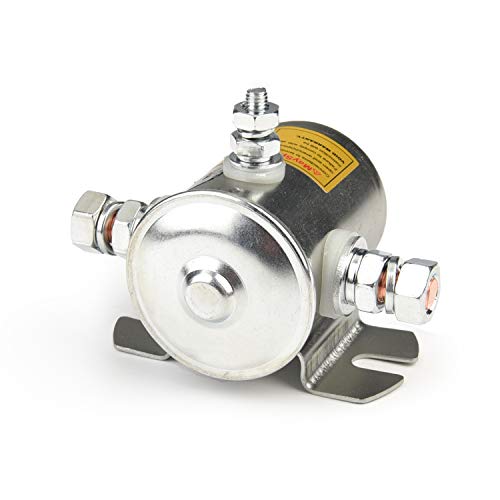
Contacts:Normally Open (NO)/ Flat Base Metal Case / 10-32 Terminal

Function: An isolator is used to combine two batteries when a alternator is charging ( engine running) and isolate them when not charging ( engine off) so you can still start your vehicle

Replacement-Exact Fit: Direct replacement for 01-00055-000/0100055000 battery disconnect relay. Intellitec systems and other 12V battery disconnect setups
Step-by-Step Wiring: Connect Main, AUX, and Ground
To wire your battery isolator correctly, follow these steps in order. First, connect a heavy-gauge cable from your primary battery’s positive terminal to the isolator’s main input port. This ensures the main battery supplies power to the system. Next, connect the isolator’s auxiliary output to the positive terminal of your auxiliary battery. Place an inline fuse on this lead near the auxiliary battery to protect against overcurrent, preventing potential damage or fire. Marine battery terminals, while corrosion-resistant, can be used in cars if they match the post size, but ensure they are securely tightened to prevent vibration-related loosening. When selecting an inverter for your auxiliary battery, consider that a 2000 watt inverter can power common boat appliances like a small refrigerator or microwave.
Then, handle the isolator’s ground wire by attaching it to a clean, unpainted metal spot on the vehicle chassis. Removing paint or rust ensures a solid electrical connection. Finally, connect the negative terminal of your auxiliary battery directly to the chassis, keeping the ground path short and efficient. Double-check all connections to ensure they are tight and secure before restoring power. The indicator light on the isolator will then confirm that everything is wired correctly and functioning properly. Always use proper tools and safety tips when securing the battery tray to prevent movement or short circuits.

【Function】——Voltage Sensitive Relay(VSR) cuts in at 13.3v and cuts out at 12.8v to ensure your main battery is always charged and ready to run your vehicle. The dual battery isolator can display the voltage, you can check the battery voltage in time

Advanced Dual Battery Isolator 12V Kit – Designed for superior performance, this dual battery kit ensures efficient power distribution between two batteries without voltage drops. Unlike traditional battery isolator diodes, this automatic disconnect switch eliminates power loss while maintaining a seamless connection between your primary and auxiliary power sources. Compact at 2.6” x 2.6” x 2”, it’s perfect for under-hood installations or as part of a battery relocation kit.

Function: The Voltage Sensitive Relay (VSR) ensures that the primary battery is always charged and ready to start the vehicle by cutting in at 13.3 volts and cutting out at 12.8 volts. When your engine is turned on and the starting battery is fully charged, the isolation will start charging the second (auxiliary) battery at the same time. Enables you to charge two batteries from one alternator at the same time.
Battery Isolator Safety: Pre-Wiring Steps You Can’t Skip
Before working on your battery isolator, always disconnect the power to prevent shock or fire hazards. Start by removing the negative terminal from the starting battery. If you have a dual-battery setup, also disconnect the auxiliary battery’s negative terminal. Keep metal tools away from exposed terminals to avoid sparks, and never smoke near the engine bay. For a reliable connection, consider using a top on/off switch to easily control power during maintenance.
Choose a dry, vibration-free location for mounting the isolator, away from engine heat. Keep cable runs short and organized to reduce resistance and potential damage. The battery chemistry influences how you handle venting—lead-acid batteries must vent gases to prevent buildup, so secure the auxiliary battery in a suitable tray or box. Confirm that the alternator’s voltage regulation matches your isolator’s specifications to ensure proper operation. For lithium-ion systems, pairing the isolator with a solar charge controller ensures optimal charging and prevents overvoltage. Use a multimeter to verify that the polarity and grounding are correct, making sure no voltage remains on the cables before reconnecting the negative terminal last, only after completing all wiring steps. For best results, choose a model specifically designed for lithium battery charging to maximize efficiency and battery life.
Where to Put Fuses and How to Choose the Right Size
For fuse sizing, you must protect the wire, not the device. Start by multiplying your alternator’s rated output by 1.5 to determine the appropriate fuse size. Then, ensure that this number does not exceed your cable’s ampacity. For example, a 70 amp isolator typically pairs with a 100 amp fuse, while a 100 amp isolator might use a 160 amp fuse. Never oversize a fuse relative to your wire’s capacity, as this defeats the purpose of short-circuit protection. Always match the fuse to the smaller value between your cable’s rating and the manufacturer’s recommended fuse size to ensure safe and effective protection. When selecting a fuse, also consider the master switch’s continuous rating to avoid a bottleneck in your power path. For instance, pairing your setup with a high-quality DC to DC charger ensures you get proper voltage regulation and performance from your alternator. Choosing the right battery straps can help secure your wiring and prevent loose connections that might compromise fuse protection.

Features: Large current thermal trip circuit breaker with manual reset switch, suitable for auxiliary DC electrical system, when the current reaches a predetermined value, the fuse can be restored to automatically disconnect and protect the circuit.

FUNCTIONS: Used to protect 48~500VDC OR 90~480VAC circuit from overload and short circuit damage and 12~48VDC from overload damage, and can also be used for control and isolation. Size: 54MM x 80MM x 75MM, Fit for 35mm DIN rail.

Reference Data: Rated for 125A current and a maximum voltage of 58V DC, this mrbf fuse has its stud size at 5/16“ (M8) and the terminal block mounting hole size at 3/8” (M10), meeting relevant circuit protection requirements
How to Test Your Isolator and Fix Common Charging Problems
To test your isolator and identify common charging problems, start by turning on your vehicle’s engine. Set your multimeter to measure DC volts. Probe the isolator’s center input post—you should see roughly 13.5 volts, indicating that voltage regulation is functioning correctly. Next, check both battery output terminals; they should read between 13.8V and 14.5V. If you notice a significant voltage drop at the auxiliary battery output, this suggests a faulty isolator or a loose connection.
If the input voltage is present but the output readings are near zero, inspect the isolator for failed diodes, which can block current flow. Ensure all wiring is compatible and connections are clean and tight; corrosion or loose wires prevent proper charging. For relay-style isolators, verify that the relay engages when the voltage exceeds approximately 13.4V. After making repairs, shut down the engine and verify that both battery banks settle separately, confirming the isolator disconnects correctly. Conduct the test again under load conditions to confirm that your system can reliably charge both batteries during actual use.