
Wondering how to wire a 24V trolling motor safely and reliably?
The key is understanding how to connect two 12V batteries in series and properly connect your motor with the right size wiring and a circuit breaker.
Getting these steps right ensures you avoid tripping your breaker or damaging your equipment.
Below, we’ll walk through the full installation process so you can do it confidently.
Why a 24V System Beats 12V for Power and Performance
A 24V system offers significantly better power and performance than a 12V setup. You get 68–90 pounds of thrust, which makes handling wind, currents, and heavier loads easier for boats up to 19 feet. The current draw drops to 24–29 amps, roughly half of what a 12V system uses, reducing strain on your wiring and components and enhancing safety. This lower power consumption allows for longer operation times, often between 4.5 and 6.5 hours at half throttle, and helps maintain consistent power under tough conditions. Additionally, the motor runs cooler, wasting less energy as heat, which simplifies battery maintenance and increases the longevity of your components. You also benefit from smoother and quieter operation with more precise control, resulting in better overall performance and a more comfortable experience on the water. To maximize this efficiency, pairing your system with high-quality battery terminals ensures minimal resistance and reliable power transfer, further protecting your investment and preventing voltage drops.
What You’ll Need for a 24V Installation
Include a trolling motor plug or receptacle for quick disconnect. This allows you to easily connect and disconnect your motor without dealing with exposed wires each time. A 60-amp circuit breaker is essential for over-current protection and should be mounted close to the positive terminal to quickly interrupt power in case of a short circuit. Use 8-gauge wire for most runs; if your wiring path is significantly longer, upgrade to 6-gauge to maintain proper voltage levels and prevent overheating. Secure all connections with self-tapping screws to ensure stability, and apply heat-shrink tubing over terminals for insulation and protection against corrosion. For maximum durability, select heat shrink tubing with adhesive lining to create a watertight seal that prevents moisture intrusion and corrosion. Finally, choose a battery charger compatible with your battery type to ensure safe and efficient charging, extending the lifespan of your system. To prevent unexpected shutdowns under load, ensure the circuit breaker is rated for sustained inrush currents that inverters and motors can draw during startup. Inspecting shore power connections for loose or corroded terminals can prevent arcing that leads to sparks and voltage drop.

Marine Accessories Set: our marine accessories set Include 1 Roll 30ft/9.14m tinned copper electrical cable, 1pcs 8 gauge 2 wire Trolling Motor Plug Receptacle, 1 Circuit Breaker for Boat Trolling Motor Marine, 10pcs 8 Awg-3/8 Ring Marine Grade Copper Wire Lugs with 10 Pcs 3: 1 shrink tubing and install the necessary accessories; Our marine tool are widely applicable to a variety of vessels, we provide multi-functional for your vessel, allowing you to enjoy worry-free sailing
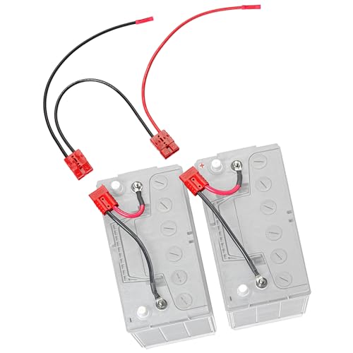
THE STRAIGHT 24V TROLLING MOTOR WIRING KIT: Two 12V batteries, one pre-built series bridge, one plug to the motor. No onboard charging leads. Built for anglers who charge off the boat or with a portable charger.

1.Marine Accessories Set: our marine accessories set Include 1 Roll 30ft/9.14m tinned copper electrical cable, 1pcs 8 gauge 2 wire Trolling Motor Plug Receptacle, 1 Circuit Breaker for Boat Trolling Motor Marine, 10pcs 10 Awg-3/8 Ring Marine Grade Copper Wire Lugs with 10 Pcs 3: 1 shrink tubing and install the necessary accessories; Our marine tool are widely applicable to a variety of vessels, we provide multi-functional for your vessel, allowing you to enjoy worry-free sailing
Step 1: Mount Both Batteries Side by Side
Mount both batteries side by side, with the positive terminal of one battery next to the negative terminal of the other. This orientation creates a shorter jumper path, making your wiring simpler and more efficient. Use straps or trays to secure each battery firmly, preventing shifting during operation. A stable mount protects cable connections and reduces strain on terminals, improving terminal protection. Ensure there is enough clearance around the batteries for cable bends and easy access to lids. Proper battery maintenance starts here—keeping the setup stable helps prevent terminal corrosion and loosening over time. Always verify the correct polarity before wiring, and arrange the layout so the final positive and negative terminals are open and ready for your trolling motor leads. This side-by-side arrangement with a short jumper path between adjacent terminals ensures efficient wiring and minimal voltage loss. For secure and consistent connections, use a quality wire stripper to prepare your cables without damaging the conductors. Before mounting, thoroughly clean the tray area to prevent corrosion and ensure a secure fit. For additional safety during use, consider installing a kill switch with lanyard to immediately cut power in an emergency.
Mount a 60-Amp Breaker Within 7 Inches of Positive
Mount a 60-amp breaker within 7 inches of the positive terminal of your battery bank. This distance is critical because it ensures that overcurrent protection is close enough to the source, complying with ABYC wiring regulations. The breaker should be installed along the wire path, not just measured straight-line distance, to account for the actual routing of the cable. This placement helps protect the entire positive wire run from the battery to the trolling motor circuit, reducing fire risk caused by short circuits. To further secure the installation, use stainless steel fasteners to avoid corrosion common in marine environments. Ensure the breaker is mounted in a dry, accessible location near the battery, using a nonconductive backing plate to prevent accidental shorts. Connect the battery positive wire to the breaker’s input, then route the output to your trolling motor. Positioning the breaker between the battery and the load is essential to meet marine safety standards and to safeguard the wiring effectively. A hot shore power cord often indicates loose or corroded connections that increase resistance and generate dangerous heat. For systems with two batteries, a high-quality dual battery isolator can automatically manage charging from the alternator.

60 AMP Circuit Breaker: Resettable 60 AMP DC (12V - 48 V) circuit breaker that replaces one-time 60A fuses in trolling motor circuits, boat fuse panels, DC breaker boxes, or inline with a marine battery switch

Protect your system: using as circuit breaker and battery Disconnect, allows to charge or maintain the battery without having to disconnect all the wires; Protect excessive current between battery or electrical from damage

Combine switching and circuit protection into single switch
Step 2: Wire the Series Jumper for 24V Correctly
To wire the series jumper for 24V correctly, start by bridging the positive terminal of Battery 1 directly to the negative terminal of Battery 2. This connection doubles your voltage from 12V to 24V, which is essential for powering most trolling motors effectively. Remember, you are only creating the series connection at this stage; the motor itself is not yet connected. Using a quality heat gun to shrink tubing over the jumper cable terminals adds insulation against moisture and corrosion.
Use a short jumper cable that has the same gauge as your main motor leads to ensure proper current flow. To protect this high-current circuit, choose the right fuse block for your boat based on the total amperage draw of the trolling motor. A reliable crimp on each terminal, made with quality crimping tools, prevents corrosion and ensures a durable connection. Secure the jumper tightly at both terminals using marine-grade hardware to prevent vibration from loosening the connection. A loose jumper can lead to voltage drops and complicate future battery maintenance, so firm, secure connections are key.
Pay close attention to polarity: Battery 1’s negative terminal remains as your bank’s negative output, while Battery 2’s positive terminal becomes your positive output. Before making this connection, ensure the motor is completely off to avoid electrical hazards or sparks. Follow the wiring diagram precisely; incorrect jumper placement will prevent your system from producing the desired 24V and could cause damage to your batteries or motor.
Step 3: Connect the Motor Leads to the Outer Terminals
Attach the motor leads to the outer terminals by first turning off the motor switch. Connect the red lead to the outer positive post on one battery, and the black lead to the outer negative post on the other battery. Confirm that the leads are correctly polarized: the red lead should be on the positive side and the black on the negative. Reversed polarity can cause damage to your motor controller, so verify the connections before tightening. Use ring terminals that sit flat under the nuts, and tighten them to a torque of around 4 N-m if specified for your components. Loose connections can lead to heat buildup and voltage drops, so ensure they are secure. Before finalizing, clean any terminal corrosion with a wire brush, then apply dielectric grease over each connection to prevent moisture buildup. Reposition rubber terminal shields to block moisture from entering exposed connections. To further extend service life, cleaning marine battery terminals with a dedicated brush and corrosion inhibitor is a proven maintenance habit. Polarity verification is crucial—double-check that the red lead is on the outer positive post and the black lead on the outer negative post to ensure safe operation before powering up the system. Using a battery tester after installation can confirm proper voltage levels and detect potential issues early. For deep cycle batteries, regularly performing a controlled desulfation charge helps restore capacity and prevent sulfate crystal buildup.
Pick the Correct Wire Gauge for Your 24V Cable Run
Choose the correct wire gauge based on your motor’s peak current and cable length. For high-thrust models drawing approximately 50A to 60A, measure the full round-trip cable length from the battery to the motor. The goal is to limit voltage drop to a maximum of 3%, which equals 0.72V on a 24V system, ensuring optimal motor performance. Always account for the total round-trip distance when measuring, as it doubles the effective resistance compared to a one-way run. To ensure a secure connection, heat shrink tubing can be used to insulate and protect each wire splice from moisture. Using a battery charger with maintainer is also recommended to keep your batteries topped off and extend their lifespan when the motor is not in use.
For example, a 15-foot one-way cable run typically requires 8 AWG wire. If your run extends to 20 feet, step up to 6 AWG, and for 25 feet, select 4 AWG. Longer distances or increased current may necessitate 2 AWG or even 1 AWG wire for safety and efficiency. Always opt for marine-grade tinned copper wire to resist corrosion.
If your calculated voltage drop exceeds 3%, increase the wire gauge by one size to maintain performance. Using a thicker wire reduces resistance, preventing voltage loss that could impair trolling motor operation.
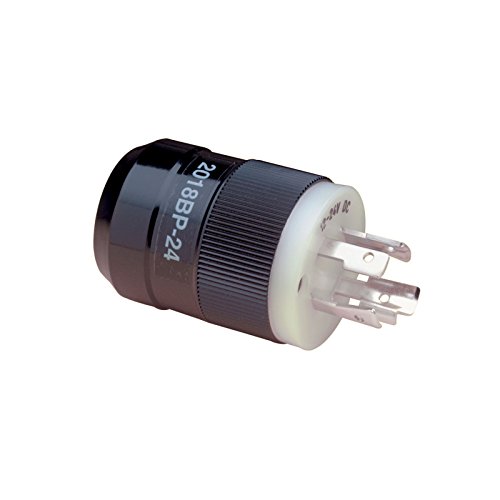
Jumper Internally To Supply 12V And 24V Power To The Trolling Motor

Safe, Waterproof & Flame-Retardant - Built for tough marine use, this trolling motor plug and receptacle features a flame‑retardant housing and a gasketed, waterproof cover that keeps out moisture, sand, and spray. Corrosion‑resistant contacts maintain a reliable 12V/24V/48V connection so your trolling motor stays powered and protected, even in rough weather.
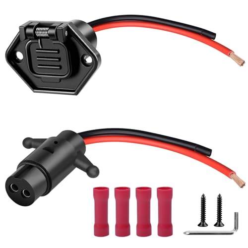
High‑Efficiency Power Transfer: Trolling motor plug 12v/24v/36v/48v & socket sets feature 8 AWG marine‑grade copper wire., which has a lower resistance than 10-gauge wire, they provide lower‑resistance, highly‑efficient power transfer for high‑power trolling motors.
Test Polarity With a Multimeter Before Powering up
Testing the polarity of your wiring with a multimeter before powering up your 24V trolling motor is essential to prevent damage. Start by setting your multimeter to DC volts above 24V. Place the red probe on the positive terminal of the battery bank and the black probe on the negative terminal. You should see a reading close to 24 volts. If the meter shows a negative voltage, it means the polarity is reversed at that point. Next, check the voltage at the plug or quick disconnect closest to the motor. The reading should match the battery bank voltage and indicate correct polarity. Test as near to the motor end as possible; a significantly lower voltage suggests wiring issues rather than just reversed polarity. Ensure the battery bank is fully charged before testing to confirm that the voltage reading accurately reflects wiring condition rather than a low charge. For reliable connections in your wiring, using quality crimping tools ensures secure and consistent contact between cable lugs and terminals. If you observe a negative reading during testing, swap the probes or correct the wiring before powering up. Ensuring proper polarity avoids the risk of frying your motor instantly.
Common Wiring Mistakes That Will Trip Your Breaker
Wiring faults that cause repeated breaker trips often stem from loose connections, incorrect wire sizing, and corrosion. Ensuring all terminals, breaker studs, and plugs are tight is essential; vibration on a boat can loosen hardware fast. Any connection you can move by hand is a sign of potential failure and should be secured. Poor or corroded wiring connections that increase resistance are a primary cause of excessive current draw.
Use heavy-gauge marine cable that matches your motor’s amperage rating and run length to prevent overheating. Undersized wiring increases resistance, generates excessive heat, and can cause nuisance trips. Regularly inspect for corrosion on terminals and connectors, which raises resistance and causes voltage drops. Cleaning buildup with a wire brush and applying dielectric grease on quick-disconnect plugs can prevent corrosion-related issues.
Lastly, confirm that your breaker matches your motor’s demands, avoiding premature trips caused by undersized or worn breakers. Check all wiring for shorts, crossed leads, or damaged insulation—these faults can trip the breaker instantly and often hide inside plugs or housings. Addressing these common wiring mistakes is critical to keeping your electrical system safe and functional.
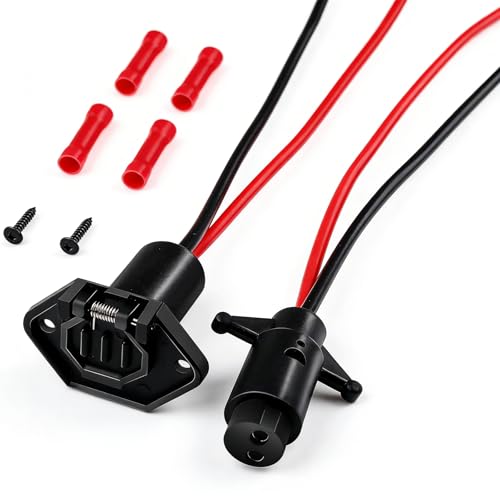
WIDE COMPATIBILITY AND VERSATILITY - Trolling motor plug is designed to be compatible with most marine boats; Whether you have small fishing boats or a larger vessel, this trolling motor connector will provide a seamless connection for your trolling motor

[SAFE AND RELIABLE] Trolling motor plug 12v-24-48v and socket housings are made of corrosion resistant and flame retardant materials with a sealed waterproof cover for waterproofing, Helps you cope with challenging marine weather conditions with ease. More than 10,000 trolling boats have already chosen ATQYZLM brand trolling motor connectors, welcome to join us.
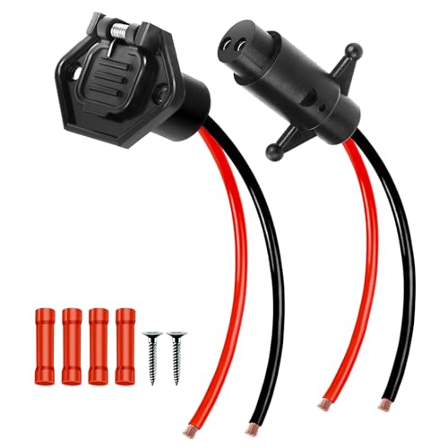
The trolling motor quick connect is made of standard U.S. 8 gauge copper wire with lower resistance,it significantly enhances battery charging efficiency and extends battery life
Run a Full-Throttle Voltage Drop Test
Run a full-throttle voltage drop test to verify your 24V system isn’t losing power under load. Start by measuring the resting voltage at the battery, aiming for about 25.2V if you’re using lead-acid batteries. This baseline helps you identify how much voltage drops when the motor is under full load. Next, crank the motor to maximum throttle and measure voltage at three key points: the battery terminals, the connector at the motor, and directly at the motor terminals. Any significant drop indicates resistance.
A voltage drop greater than 0.5V at the battery suggests weak cells rather than wiring issues. Conversely, a drop exceeding 0.2V at any single connection signals resistance likely caused by corrosion, loose terminals, or frayed wiring. Regularly inspect and maintain your battery posts and cables. If the total voltage loss from battery to motor exceeds 5 percent, roughly 1.2V, you’re wasting power as heat and should address the issue before relying on the system.

SAFETY FIRST: It will send out multiple alarms through sound and light. When the voltage is detected, the tip will send out red light and beep. When the higher the sensed voltage is, or the closer it is to the voltage source, it beeps at a higher frequency and the percentage value will be larger. At the same time, the screen will be red or green, red means high voltage and live wire are detected, green means low voltage and null wire are detected

Neon Light Indicates Presence Of Ac Voltage From 80-250 Vic

【NCV】Non contact voltage tester provides the easiest and safest way of checking for electrical current in a wire, outlet, switch or lamp that has mysteriously stopped working.