
Wiring your boat safely can seem complicated, but knowing the basics makes all the difference. Proper wiring not only keeps your boat running smoothly but also prevents dangerous electrical fires and corrosion.
When you follow the right standards, your gear and systems will work reliably for years to come. Keep reading to learn the key steps to wiring your boat the right way.
Why Every Boat Owner Needs ABYC E-11 Wiring Standards
Electrical failures are a primary cause of onboard fires, making adherence to ABYC E-11 wiring standards essential. This standard ensures your wiring is properly sized and connections are secure, significantly reducing the risk of sparks and fires caused by undersized or loose wiring. Proper overcurrent protection, such as correctly rated circuit breakers and fuses, prevents wires from overheating and short circuits, which are major fire hazards. Wiring should be sized correctly for your load—using the right gauge of marine-grade tinned copper wire helps minimize resistance and heat buildup under operation. These wires resist saltwater corrosion better than standard wire, increasing your system’s longevity. Using a best negative battery cable with a secure ground connection is equally vital for preventing voltage drops and ensuring reliable circuit completion. Following E-11 guidelines also ensures critical systems like navigation lights, bilge pumps, and safety equipment operate reliably. Maintaining tight voltage-drop limits is part of this standard, so your essential electronics function properly even in harsh conditions. Neglecting these standards increases the risk of weak or failing systems, especially when you need them most. For solar-powered setups, a charge controller must be properly integrated to regulate energy from panels and prevent battery overcharging. Adopting ABYC E-11 wiring standards is a key step toward a safer, more reliable boating experience. Choosing a properly rated master switch is equally critical for isolating battery power and preventing accidental short circuits.

Heavy Duty 16 Gauge Marine Wire:Our 16 AWG marine wire is made of tinned copper to make sure good conductivity,corrosion resistance, high durability,flexibility,stability for a long-lasting performance

High Quality:Our marine wire is made of tinned copper to make sure good conductivity,Anti-corrosion, high durability,flexibility,stability for a long-lasting performance

High Quality:Our marine wire is made of real copper strands and tinned to make sure conduct well,resist corrosion, high durability,flexibility,stability for a long-lasting performance
What Exactly Is ABYC E-11 and What Does It Cover?
ABYC E-11 specifically governs the wiring systems on boats, but it does not cover every aspect of electrical installation. It excludes wiring for outboard engines located inside the engine cowling and any management systems supplied directly by the engine manufacturer. For the rest of your vessel’s electrical wiring, such as the wiring from the distribution panels to bilge pumps and lighting, E-11 serves as your primary reference. For example, when installing a trolling motor, E-11 provides guidelines for selecting the proper circuit breaker size based on the motor’s amperage draw. Marine surveyors and builders rely on this standard to verify proper overcurrent protection, grounding methods, and correct labeling. Following E-11 helps ensure that your boat’s electrical system aligns with industry safety practices and reduces the risk of electrical faults or fires. When selecting components, choosing high-quality battery terminals is critical for maintaining reliable power connections and preventing voltage drop in marine wiring systems. Following best practices for installation includes replacing marine battery terminals safely to avoid loose connections and corrosion.
ABYC Wiring Standards: How to Match Wire Size, Fuse Size, and Load
To match wire size, fuse size, and load, always start with choosing the wire first. The circuit protection must safeguard the conductor, not just the device being powered. Begin by determining your load: multiply continuous loads by 125% to establish your minimum protection requirement. Measure the full round-trip length of the wire run to select a wire size that limits voltage drop and meets ampacity standards. The fuse size must be at or below the wire’s ampacity — oversizing the fuse can bypass the conductor’s protection. Opt for the smallest standard fuse above your calculated load, ensuring it doesn’t exceed the wire’s current-carrying capacity. For portable or backup radio setups, a dedicated battery box helps organize connections and protect the battery terminals. This approach guarantees a safe, reliable system on your boat, preventing overloads and potential damage. Following the proper connection sequence ensures the shunt is wired in series on the negative side of the battery for accurate monitoring. Always follow ABYC wiring standards for proper battery charging and installation.

Safety LED Indicator Design --- The red warning light on the 12 volt fuse block will light up immediately when the corresponding fuse is blown. This fuse box 12V could help you easily figure out the short circuit or any other fault and fix the error in time, greatly ensuring the normal operation of your device and the circuit.
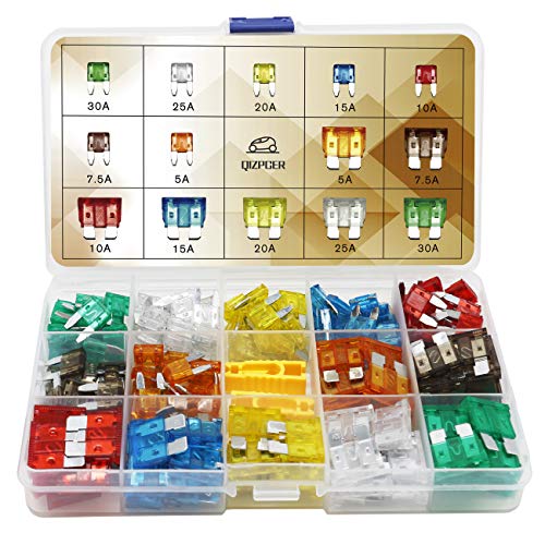
Easy Identification: Made of a high quality zinc alloy, with a transparent cover and color coded
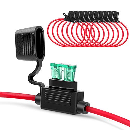
SAFETY PROTECTION: Heavy duty 14 gauge (AWG) red color wire, great look and added protection to the circuit
How ABYC Wiring Standards Specify Marine vs. Household Wire
ABYC wiring standards specify marine-grade wire as a requirement, distinguishing it clearly from household building wire. Marine wire must have stranded, tinned copper conductors instead of the solid copper used in typical home wiring. This choice is essential because solid wire cannot withstand the constant vibration and repeated flexing present on a boat, which can cause cracks and electrical failures over time. Additionally, marine insulation must be highly durable, resisting moisture, salt, oil, and UV exposure—conditions your home wiring isn’t built to endure. Proper marine wiring also demands flexibility to accommodate boat movement and engine heat without degrading. Avoid using extension cords or THHN building wire for marine applications; instead, look for jacket markings indicating UL 1426 boat cable. This ensures the wire’s corrosion resistance and reliability in wet, vibrating environments, providing long-term safety and performance. A common cause of inaccurate readings from onboard systems is induced resistance from corroded connections, which directly relates to why battery monitor inaccuracy often stems from using non-marine wire that fails in damp, salt-laden environments.

High Quality:Our marine wire is made of tinned copper to make sure good conductivity,Anti-corrosion, high durability,flexibility,stability for a long-lasting performance

High Quality:Our marine wire is made of tinned copper to make sure good conductivity,Anti-corrosion, high durability,flexibility,stability for a long-lasting performance
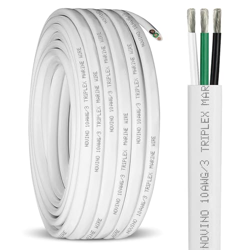
High Quality:Our 10/3 marine wire is made of tinned copper to make sure good conductivity,Anti-corrosion, high durability,flexibility,stability for a long-lasting performance
Wiring Support Rules Under ABYC Standards for Wet Boats
Use nonmetallic clamps or marine-rated cable ties to hold conductors securely without crushing them. Ensure the fasteners are designed for marine environments and can withstand exposure to water, oil, and gasoline. When securing a section under a metal strap, cover it with loom or tape to prevent chafe and protect the wiring from abrasion. Avoid using hardware-store ties or ordinary nylon zip ties, as they may degrade faster and fail under moisture and chemical exposure. Proper support materials will resist osmotic damage and keep your wiring in place despite the constant motion and dampness common on wet boats. Selecting the right crimping tool is also essential for reliable connections, and using a quality crimping tool ensures consistent terminal attachment under these harsh conditions. A top crimping tool for non-insulated terminals delivers reliable terminal attachment through precise die alignment and compression force. For battery wiring, a charger that follows lithium battery charging standards ensures proper voltage and safety compliance.
Grounding vs. Bonding: ABYC’s Fault Protection Rules
Grounding and bonding serve distinct, non-interchangeable roles in your boat’s electrical safety system. Grounding provides a low-impedance path for AC faults, ensuring that dangerous faults trip breakers or ELCIs quickly. Bonding, however, interconnects underwater metals to equalize potential and help control corrosion. For example, the weight of marine batteries can influence how you mount them, but their mass does not change the separate wiring requirements for grounding and bonding. Unlike fuses, circuit breakers can be reset after a fault, making them more convenient for repeated use on a boat. A proper battery isolator prevents your starting battery from being drained by house loads while still allowing simultaneous charging.
You need circuit redundancy here: grounding shields people from electric shock, while bonding protects your hull from galvanic damage. For system compatibility, keep your AC grounding conductor continuous with no switches or fuses interrupting it. The bonding network should connect to your grounding structure at only one point. Don’t confuse the two—grounding clears faults when they occur, bonding prevents faults from forming. Each system must maintain its own integrity to ensure your boat stays safe and seaworthy.
Shore Power: What E-11 Says About Your Dock Cable
A dedicated shore power cable is considered part of your boat’s AC electrical system, extending from your inlet to the dock outlet. It needs to be outdoor-rated and flexible, such as a SOW or STW type, not a household extension cord. Both ends must lock securely and be properly grounded. The shore-end plug should match the pedestal outlet, and the boat-end female connector must fit your inlet. A loose connection or worn prongs are among the most common causes of sparking when plugging in. Avoid using splices or adapters, as they increase the risk of cable faults. The grounding conductor must remain green and separate from the neutral conductor onboard because the neutral is already grounded at the dock. Maintaining this separation is crucial for safety; it prevents you from creating a neutral-ground bond that could compromise fault protection. When selecting components for your system, consider the same principles used for marine battery terminals that prioritize secure, durable connections to avoid faults. Just as with those terminals, using adapter-style connectors on your shore power cable can introduce weak points, so it is vital to choose components with high-quality locking mechanisms to maintain a safe, continuous ground path. Treat your shore power cable as a vital safety device—anything less can jeopardize your boat’s electrical safety.

WEATHERPROOF CONSTRUCTION: Watertight molded plug and connector; corrosion resistant nickel plated contacts

WEATHERPROOF CONSTRUCTION: Watertight molded plug and connector; nickel plated contacts resist corrosion in marine environments

Marine and Boat Shore Power Cord: 125v 30 Amp extension cord made by the Marine & RV power experts. RV MUST have Twist lock
5-Step ABYC Wiring Check Before Your Next Project
Running a five-step ABYC wiring check before your next boat project is essential for safety and reliability. First, inventory every circuit by mapping each wire from the source to the load. Record the exact conductor gauge and wire color to ensure consistency. Confirm circuit labeling at its origin, not just at the panel, so you know exactly which switch or breaker controls each circuit. Second, verify that you are using marine-rated stranded copper wire; avoid household solid wire as it lacks the flexibility and insulation needed for marine environments. Third, protect every battery positive, alternator, and charger output with a fuse or breaker placed as close as possible to the power source. This prevents potential fires or damage from short circuits. Fourth, thoroughly inspect grounding and bonding connections for corrosion, which can compromise system safety. Additionally, ensure that a distinctive and easily accessible shutoff can be quickly identified in case of emergency. Finally, test GFCI receptacles, reverse-polarity indicators, and look for signs of chafe or heat damage in wiring. A marine fuse block should be wired with correct routing and connections per safety guidelines. Address these corrections before energizing your system to prevent hazards and ensure smooth operation.

HIGHLY CONDUCTIVE: NAOEVO electrical wire uses high-precision oxygen-free tinned copper, The outside diameter of the Jacket is 2.7 mm Typ, and 41 strands of 0.14 mm tinned copper wire are inside each circuit, has lower resistance and higher conductivity

Tinned Copper Construction: Each conductor is built from 2x26 strands of 0.25mm oxygen-free tinned copper, rated to 600V for demanding low-voltage circuits. The tin coating resists corrosion from salt spray, moisture, and battery acid, extending wire life in marine and outdoor environments. Inside the white PVC outer jacket, red and black conductor sheaths make polarity identification instant; the white jacket also makes routing easier to trace during installation and inspection

10Gauge Silicone Wire 10ft --- (5Feet Red + 5Feet Black)